

blog
Cable Glanding vs. Termination: What’s the Difference?


Cable glanding and cable termination are often mentioned together, and it’s easy to see why. Both are part of installing a cable into an electrical enclosure, but they involve different steps.
Glanding deals with how the cable enters the enclosure. The cable gland holds the cable in place, provides a seal against dust and moisture, and, where armored cables are used, can provide electrical continuity between the cable armor and the enclosure.
Termination starts once the cable is inside. It involves preparing the conductors, stripping the insulation, crimping lugs or fitting connectors, and making the final electrical connections. Both jobs need to be done properly. A well-installed gland won’t make up for a loose termination, just as a good electrical connection won’t prevent problems caused by a poorly fitted gland.
At Hoonsun Cable Gland, we manufacture cable glands and connectors used in control panels and electrical equipment across industries such as rail, energy, and industrial automation. When customers ask us about cable glanding, the issue often turns out to involve more than the gland itself. Cable preparation, conductor connections, and the way the cable is secured inside the enclosure can all affect the finished installation.
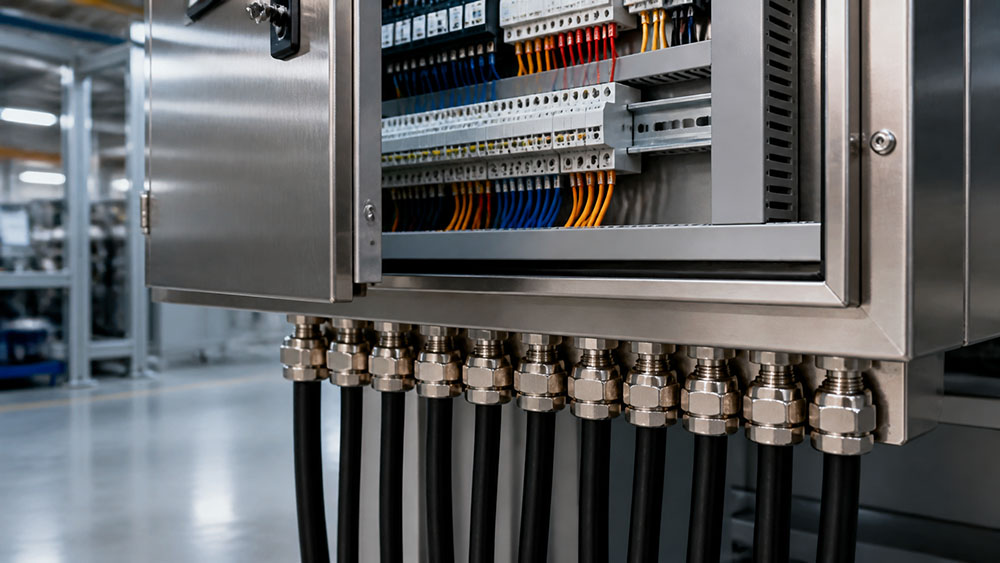
What Is Glanding
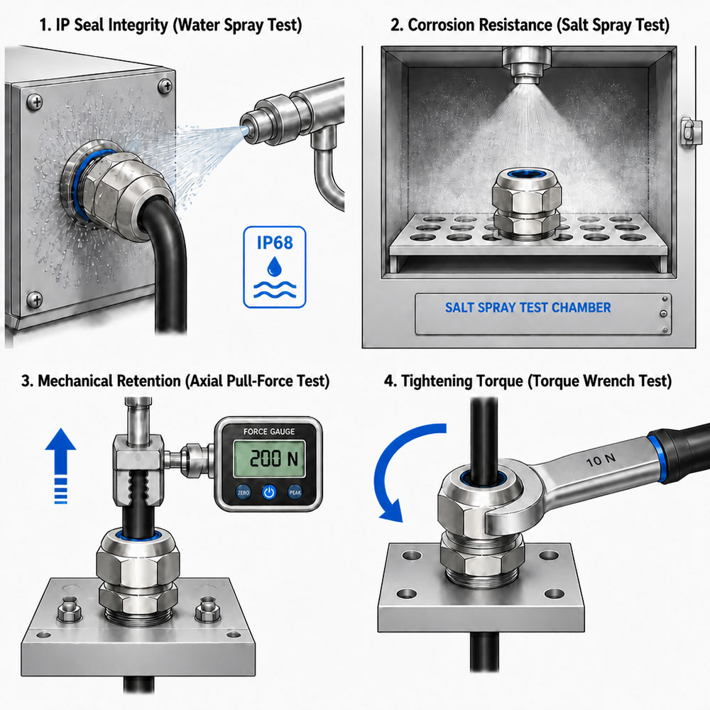
Glanding is the mechanical and environmental side of the entry. It starts with the enclosure hole and the thread that engages it, continues through the sealing ring that grips the cable sheath, and ends where the sheath is clamped and the armor or braid is landed. The steps themselves follow the installation standards most projects are audited against. The three outcomes that matter are a seal that holds its IP rating, a strain relief that keeps movement off the conductors, and a bond that gives fault current a low-impedance path to earth.
Everything in that list is checked by hand and by eye. A gland with the right size but a crossed thread will leak, and the wrong sealing insert passes a visual check and fails a hose test.
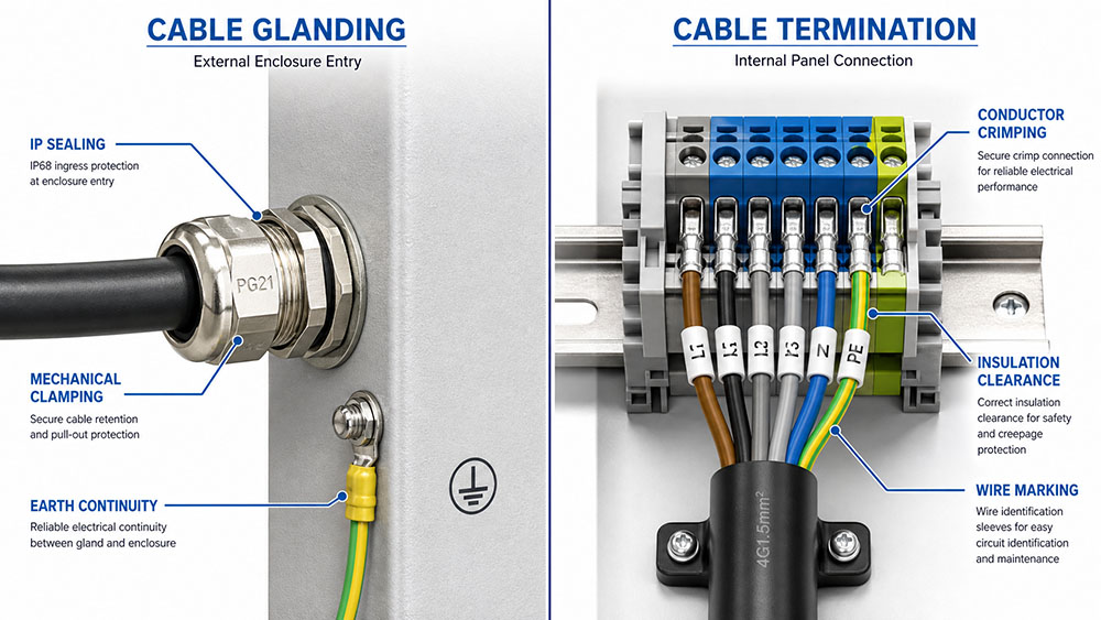
What Is Termination
Termination begins where the sheath stops. It covers conductor preparation, the crimp or lug that joins the conductor to the terminal, the insulation distance around that joint, and the marking or ferrules that identify each core. On armored and screened cable the screen or drain wire is usually landed here too, at the earth bar rather than at the gland.
The two scopes meet at a single point, where the sheath is cut back. Get that length wrong and either the cable clamp has nothing to grip or the conductors are too short to reach the terminals.
Why the Two Are Specified Separately
Cable glanding and termination are usually listed as separate tasks in installation schedules because they involve different work and inspection requirements.
For glanding, the main concerns are whether the cable gland is properly fitted, maintains the required IP protection, and provides reliable earth continuity where needed. Termination focuses on the electrical connections, including crimp quality, connection security, contact resistance, and adequate clearance between conductors.
Keeping these checks separate makes it easier to identify problems during inspection. A properly crimped connection doesn’t mean the cable entry is sealed correctly. Likewise, a well-installed gland doesn’t guarantee that the conductors have been terminated properly.
The distinction also matters when estimating installation costs. Cable glands are selected according to cable size, material, and protection requirements, while termination work depends largely on the number of conductors and the type of connections involved. A cable with forty cores, for example, takes considerably more time to terminate than one with just a few cores, even if both use a similar gland.
For a closer look at the components used in each process, see our guide to the differences between cable glands and cable terminals.
Installation Sequence: Glanding and Termination
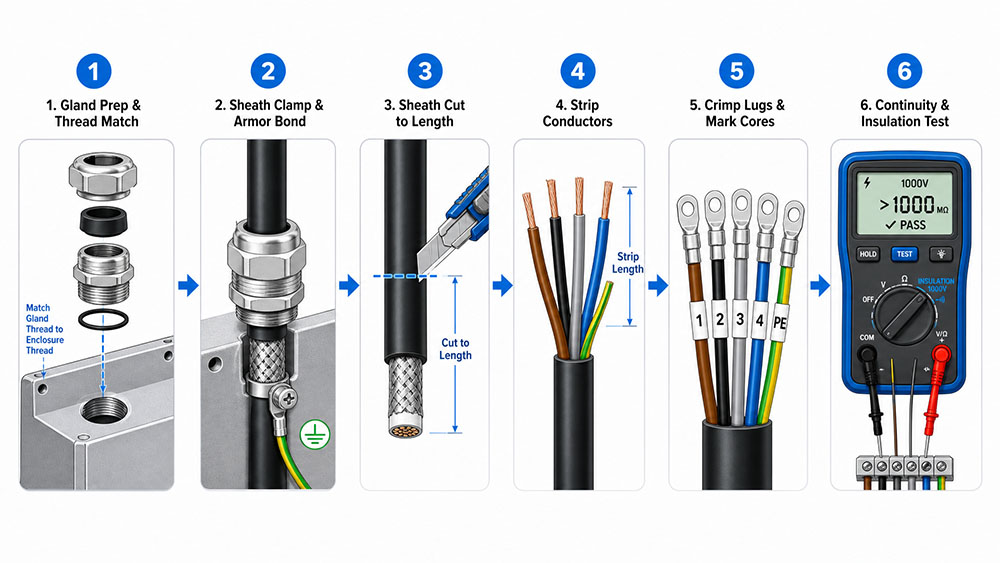
The sequence below is the one that avoids rework, and it is the sequence our installation guidance follows.
| Step | Scope | What Has to Be True Before Moving On |
|---|---|---|
| 1 | Glanding | Hole and thread match, sealing washer seated, locknut inside the wall |
| 2 | Glanding | Sheath clamped, armor or braid landed, gland tightened to spec |
| 3 | Shared | Sheath cut back to the length the terminal block needs |
| 4 | Termination | Conductors stripped at the crimp length, no nicks in the strands |
| 5 | Termination | Lugs crimped and seated, ferrules fitted, cores marked |
| 6 | Shared | Continuity and insulation tests repeated on the finished joint |
Steps three to five are where most avoidable defects sit, because the pressure to close a panel arrives right after the gland work is done.
Where Glanding Fails the Termination Test
Three failures cross the boundary in ways that are easy to miss on a finished panel.
1. Sheath Cut Too Long
The sheath is cut too long, so the clamp has nothing to grip and the strain relief stops working. Cable then moves inside the gland every time the door opens, which eventually works the conductors loose at the lug, and the step-by-step installation walkthrough shows the clamp depth that avoids it.
2. Shield Grounded at the Wrong Interface
The shield is landed at the gland instead of the earth bar, or landed at both ends when the design calls for one. On drives and instrumentation that shows up later as noise on a signal that tested clean on the bench.
3. Over-Tightened Cold-Flow Sheath
The gland is over-tightened to reach a torque figure on a cable whose sheath cold flows, and the sealing ring deforms. The termination is untouched and looks perfect, while the entry no longer holds its rating.
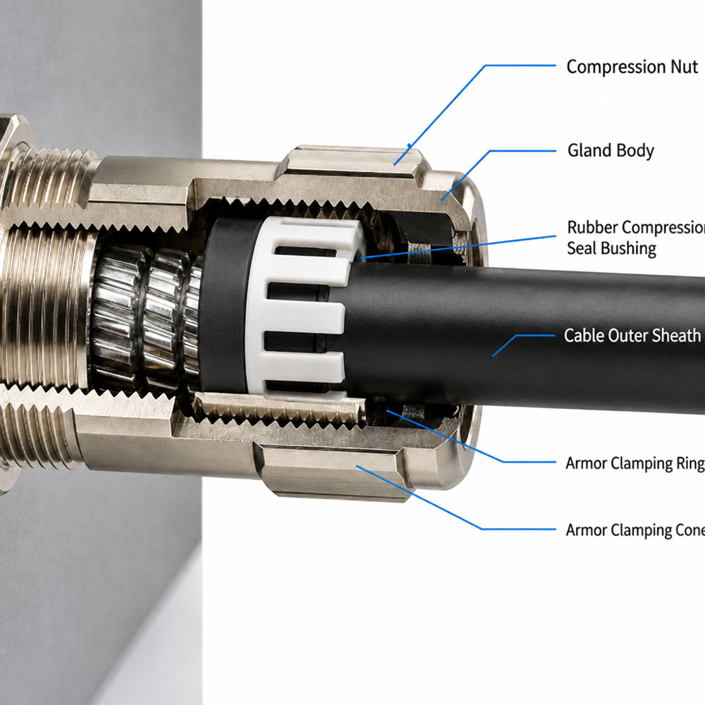
On armored cable the bonding path through the gland body depends on how the armor is clamped. Our guide to metal cable glands shows the parts that do that work, and the parts guide explains each contribution.
Inspection Points for Both Scopes
| Check | Glanding | Termination |
|---|---|---|
| Seal integrity | Hose test or visual on the sealing ring | Not applicable |
| Bond continuity | Gland body to enclosure, under 0.1 ohm target | Shield to earth bar |
| Mechanical hold | Pull test on the sheath clamp | Pull test on the lug |
| Dimensional | Thread engagement and protrusion inside the box | Clearance distance at the terminal |
Two of those four are worth doing on the first unit of every batch rather than at the end. A locknut that sits proud of the wall by a millimeter changes the thread engagement on every gland behind it, and the correction is far cheaper before the panel is wired.
Frequently Asked Questions
Is glanding part of the termination?
No. Glanding ends at the sheath clamp and the armor bond, while termination starts at the conductors. On site the two are often done by the same person, which is why the distinction gets lost.
Does the gland count as the earth connection?
Only where the design says so. Brass glands provide a bond path through the body, but a separate earth conductor or a grounding plate is what most standards-based inspections ask to see on a completed panel.
What length should the sheath be cut back to?
Long enough for the cores to reach the terminals with a service loop, and short enough that the clamp still grips sheath rather than tape. Measure from the gland exit to the terminal block, then add the loop the drawing specifies.
Can glanding be inspected after the panel is wired?
Partly. The seal and the bond can still be tested, but the sheath cut length and the armor landing are hidden once the terminal cover goes on, so they have to be checked before wiring starts.
Conclusion
Glanding and termination share a single boundary and very little else, which is the reason to keep them separate in both the schedule and the inspection plan. The gland owns the entry and the bond, the termination owns the conductors, and the cut length at the sheath is the one measurement that decides whether both can succeed.
If a panel is failing at that boundary, send us the gland size, the cable construction, and the way the armor or shield is being landed. We will tell you which side of the joint is actually causing it.
How Can We Help You?
Our professional team is ready to provide you with prompt and support.

As a trusted cable gland supplier, our connector products serve international markets, including new energy, rail transportation, outdoor lighting, robotics and automation, industrial electrical cable equipment, and computer superservers.
© Copyright 2026 ZHEJIANG HONGXIANG CONNECTOR CO., LTD .