

blog
Heavy Duty Connector Selection: Size, Inserts, and Locking Types


What Makes a Connector Heavy Duty
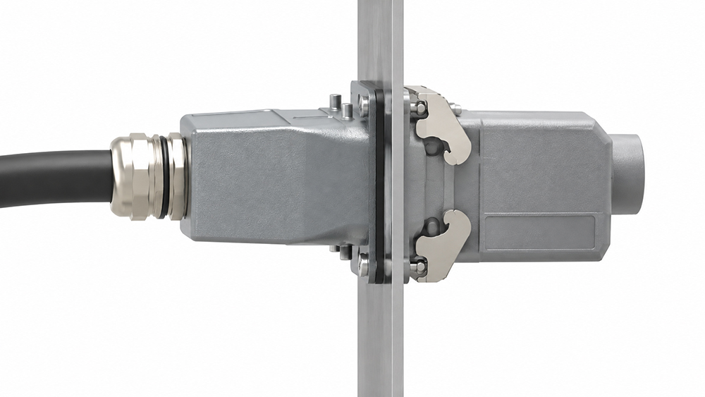
Heavy-duty connectors are built for high-voltage and high-current work in environments where a standard plug would not survive. Our range is rated IP65 to IP68, which covers washdown, dust, and temporary immersion depending on the version ordered.
The housing is the first difference. Die-cast aluminum alloy shells handle impact and heat, while high-performance thermoplastics suit lighter frames where weight or chemical exposure matters more. Both carry the same internal modular concept, allowing a power insert and a signal insert to share one unified frame.
Contacts are plated in nickel, silver, or gold according to the required duty. Nickel handles general industrial use, silver is selected for higher-current paths, and gold appears where contact resistance must remain stable across long idle periods and low signal levels.
Shell Size Comes From the Cable and the Contacts
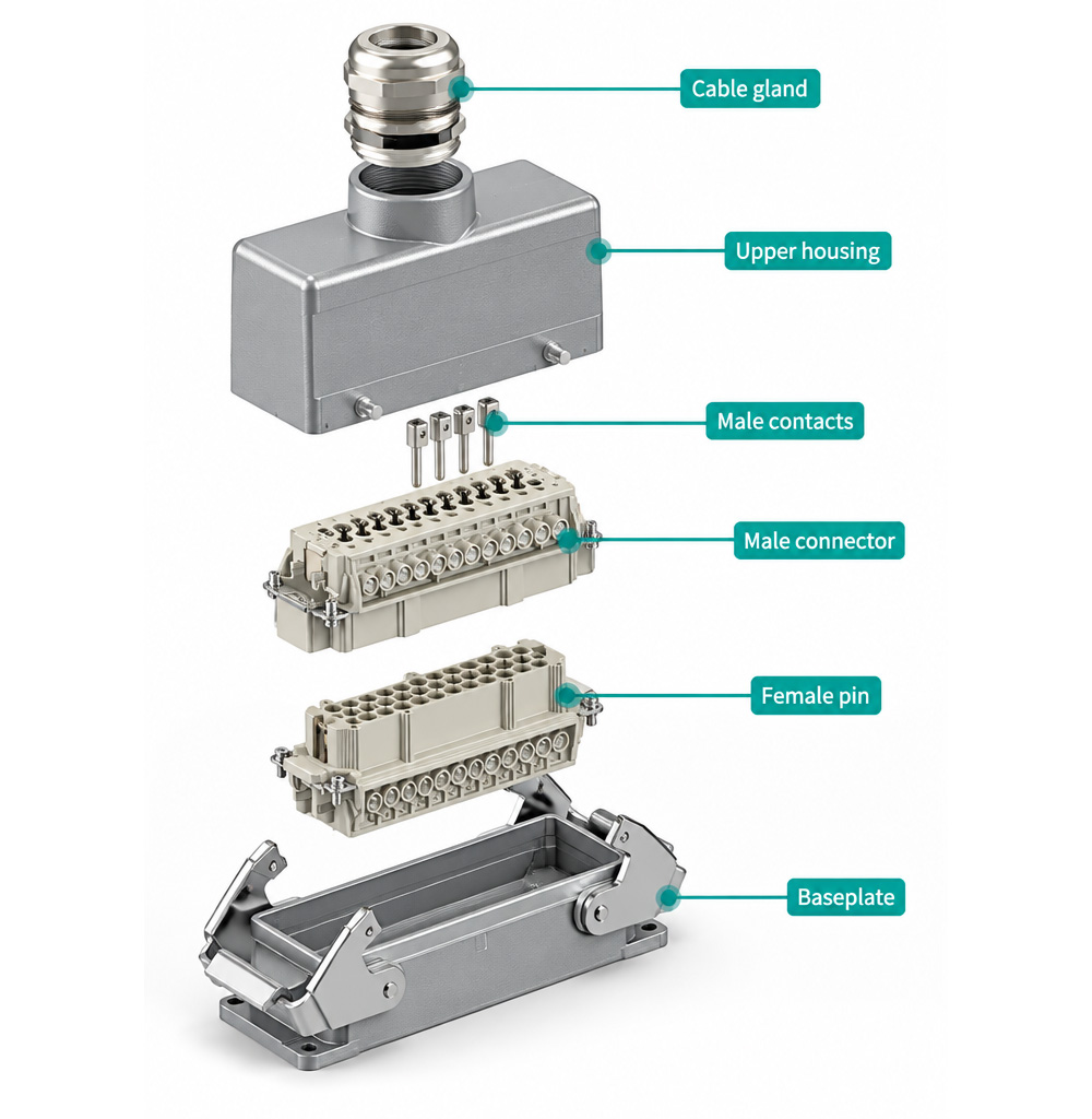
Shell size is determined by two inputs that pull in opposite directions. The cable bundle at the entry sets the minimum size, since every core and cable gland must pass cleanly through the hood. The insert count sets the practical maximum, because a large shell filled with a small insert wastes valuable space and budget.
The sequence that works best on new builds is to fix the core count first, select the insert that carries it, and then choose the shell that frames that insert. Retrofits run in reverse, because the shell is already mounted and the replacement insert must conform to it.
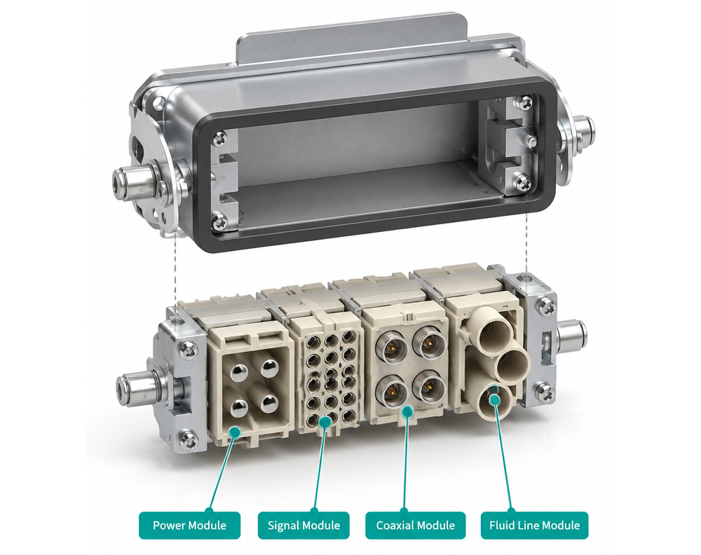
The modular design helps here. Inserts support anywhere from a few contacts to several dozen, and mixed frames combine power, signal, coaxial, and even fluid lines in one housing, allowing a machine to add a sensor run without drilling a second connector port.
Insert Layout: Power, Signal, and Mixed Frames
| Frame Type | Typical Duty | What Decides the Choice |
|---|---|---|
| Power only | Motor feeds and supplies | Current per contact and the number of poles |
| Signal only | Control and instrumentation | Contact density and screening needs |
| Mixed | Machine head with power and feedback | Ratio of power to signal contacts, and the insert partition |
| Fluid capable | Coolant or hydraulic lines in the same hood | Whether the fluid path shares the frame or needs its own |
Mixing is where most mistakes happen, and they are layout mistakes rather than hardware failures. A frame that places a high-current contact right beside a low-level signal contact passes continuity tests on the bench and still picks up operational noise, because the partition between inserts provides less isolation than the designer assumed.
Locking Type and Vibration
| Locking | Best Fit | Weak Point |
|---|---|---|
| Threaded coupling ring | High-vibration frames, permanent machine wiring | Slower to open during routine service |
| Bayonet | Frequent mating cycles and quick changeovers | Requires full engagement to seal correctly |
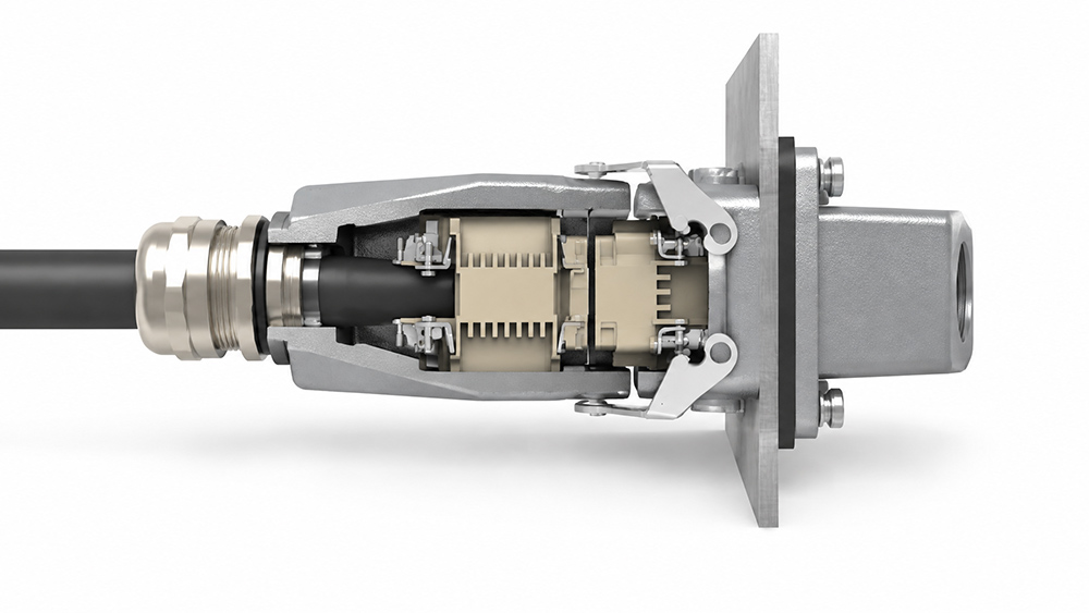
| Lever | Large shells and dense inserts | Lever clearance must be planned at the panel door |
On equipment that moves, the locking method matters more than the ingress rating in the first year of operation. A threaded ring that backs off under vibration breaks a seal that was never faulty, and a bayonet half-turned reads as connected while the internal seal remains unseated.
For stationary control panels, the lever type earns its extra depth allowance by drawing dense inserts together smoothly and evenly.
Materials and Ingress Protection
IP65 to IP68 represents a range rather than a single fixed rating, and the specific version ordered determines the performance delivered. A high-pressure washdown environment demands the sealed variant combined with a matched cable entry that preserves that rating, bringing proper cable gland selection to the forefront.
Chemical- and oil-rich environments are managed through the housing material and sealing compound working together, meaning coolant-exposed atmospheres require both to be explicitly specified. Our circular connectors apply identical sealing logic within a cylindrical shell profile.
Liquid-cooled equipment takes this discipline further. Where machinery routes fluid directly to tooling, our liquid cooling connector range shares the mounting standards of heavy-duty frames, and our guide to liquid cooling connectors explains where fluid and electrical architectures diverge.
Where Heavy Duty Connectors Earn Their Cost
Industrial Automation Cells
Machine heads and robotic tools can be swapped out without rewiring, converting an expensive multi-day changeover into a streamlined one-hour turnaround.
Energy Distribution Systems
A single compact housing routes multi-phase power alongside critical supervisory control signals across one certified, ruggedized interface.
Skid-Mounted Process Equipment
Connectors engineered specifically for continuous vibration eliminate intermittent ground and signal faults that are notoriously difficult to diagnose.
How to Choose the Right Connector Configuration
Start by checking the number of contacts required and the current each contact needs to carry. This will help you narrow down the available inserts. You’ll also need to consider whether power and signal connections should be separated and how much space is available for wiring.
Once you’ve selected the insert, check which housing sizes are compatible. The housing needs to fit the mounting space and provide enough room for the cable connections. From there, you can choose a locking mechanism based on how the connector will be used, particularly if it needs to be disconnected regularly.
Before finalizing the selection, confirm the connector’s electrical ratings, environmental protection, and cable entry requirements. It’s best to check these details before making any cutouts in the enclosure, as changing the housing size later may require additional modifications.
Frequently Asked Questions
How do I choose between die-cast aluminum and thermoplastic heavy-duty connector housings?
Select die-cast aluminum alloy housings for harsh industrial applications demanding mechanical impact resistance, high structural rigidity, and thermal endurance. Choose high-performance thermoplastics where weight savings or aggressive chemical washdown environments take priority.
Can power and sensitive signal circuits share the same heavy-duty connector frame?
Yes, modular mixed frames accommodate both power and signal lines. However, adequate physical shielding or internal partitioning must be verified to prevent electromagnetic interference and cross-talk from high-current conductors into low-voltage signals.
Which locking mechanism is best for severe vibration environments?
A threaded coupling ring provides the highest mechanical retention against continuous vibration on machinery. Lever-lock styles work best for dense inserts and quick maintenance on stationary control panels, while bayonet mechanisms suit frequent mating cycles.
What is the proper design sequence when specifying shell size and insert layouts?
On new equipment designs, first establish the conductor core count and current requirements, select the modular contact insert, and finally choose a compatible housing shell that fits enclosure space and cable entry glands.
Conclusion
Choosing the right heavy-duty connector comes down to matching the insert, housing, and locking mechanism to your equipment. The number of contacts and current requirements will help determine the suitable insert, while the housing size, cable entry, and locking type should match the available installation space and operating conditions. Checking these details before installation can help avoid compatibility issues and make future maintenance easier.
Need customized connector sizing or engineering pinout guidance? Contact our engineering team with your cable schedule, required pole count, and panel mounting dimensions.
How Can We Help You?
Our professional team is ready to provide you with prompt and support.

As a trusted cable gland supplier, our connector products serve international markets, including new energy, rail transportation, outdoor lighting, robotics and automation, industrial electrical cable equipment, and computer superservers.
© Copyright 2026 ZHEJIANG HONGXIANG CONNECTOR CO., LTD .