

blog
Cable Gland Locknuts and Earthing: Installation Basics


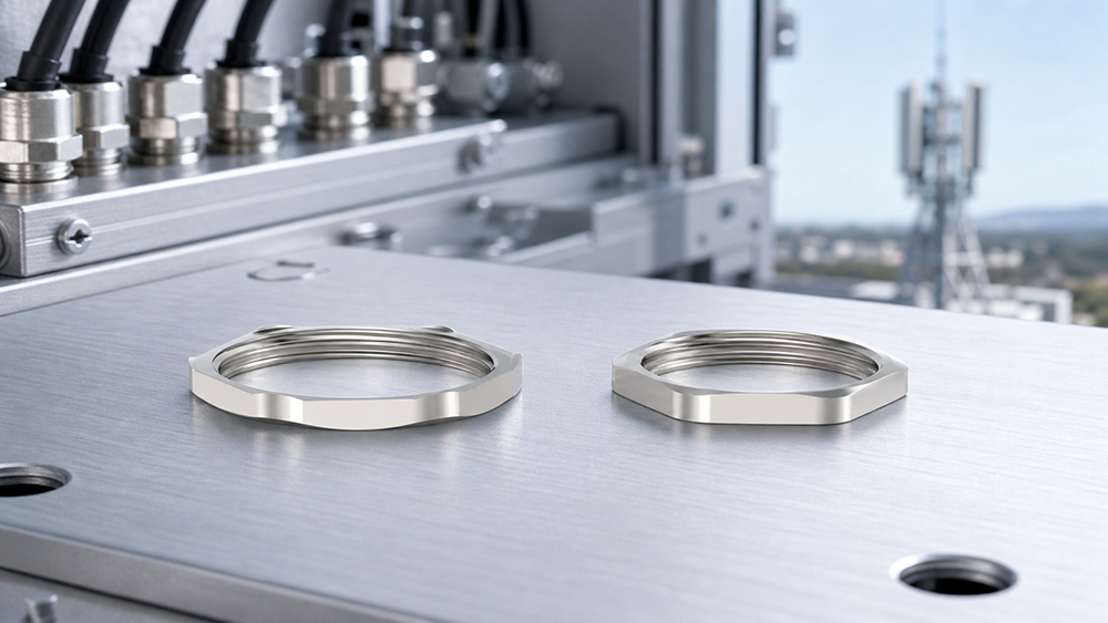
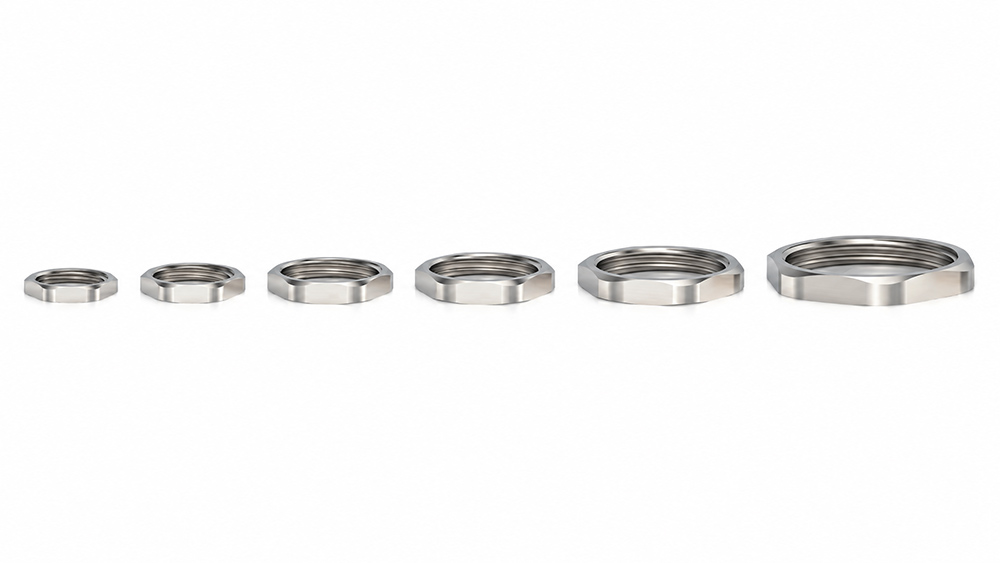
A cable gland locknut may be a small part of the assembly, but it plays an important role in keeping the gland securely fitted to the enclosure. It holds the gland in position against the enclosure wall and helps prevent it from loosening during installation or use.
For applications that require electrical continuity, a serrated locknut can help establish metal-to-metal contact by biting through paint or surface coatings. A standard locknut may look similar once installed, but it does not provide the same contact with a coated surface. This can become an issue during earth continuity testing.
The Role of Locknuts in Cable Gland Installation
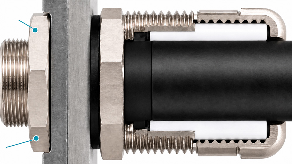
A gland is threaded and tightened from outside. Without a nut on the inside face, the whole assembly depends on the enclosure wall taking the torque, and on thin sheet that means distortion rather than a seal. The locknut spreads the load across a wider bearing area and locks the gland at the depth the wall allows.
That function explains the two dimensions on every locknut data sheet. Thickness sets the bearing area, and spanner size sets the tool access behind the panel. On a crowded back plate the second matters more, because a nut that cannot be reached with a spanner gets tightened with pliers and ends up out of square.
Plain Locknut or EMC Locknut
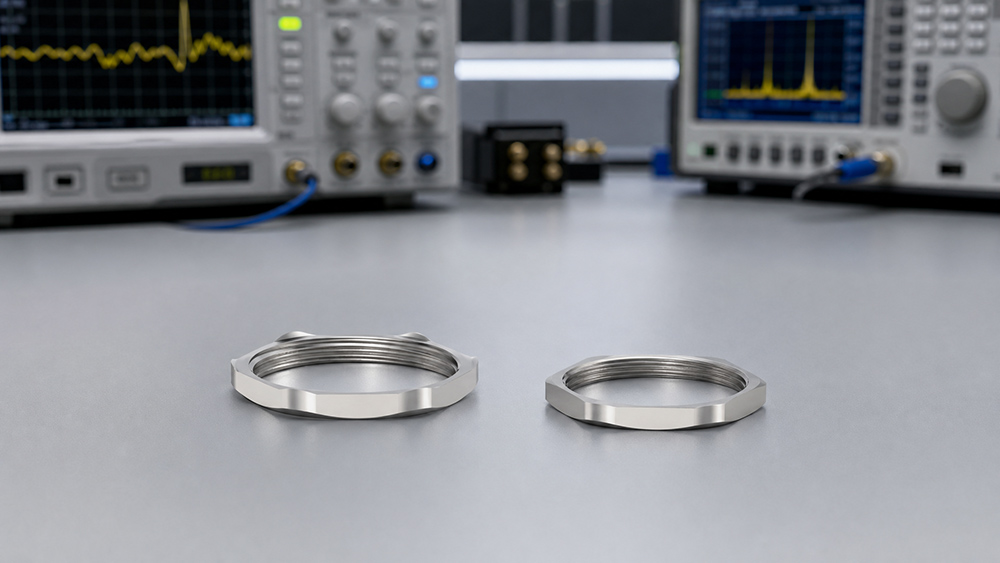
The plain version is a hex nut in nickel plated brass with a flat face. It does the mechanical job on a painted or unpainted wall where the earth path is provided elsewhere, which covers most panel work where a stud and a bonding conductor are already specified.
The EMC version carries serrations on the bearing face. Those edges cut through powder coat, anodizing, and paint to reach bare metal, which is what closes the bonding path through the enclosure rather than through a separate conductor. Both types are available across the same thread families, and our EMC locknut range lists them with the same code structure as the plain parts so a mistake is visible on the order line.
Choose the serrated part when the gland body carries the bond, when the wall is coated, and when the panel carries drives or screened cable. Choose the plain part where a dedicated earth conductor already lands on a stud nearby, since a serrated nut there only scratches paint.
Thickness and Spanner Size by Thread
The table below matches our standard locknut series. The EMC parts share the same spanner sizes, so a plain nut can be swapped for a serrated one without changing tools.
Standard Plain Locknut Parameter Table
Metric Thread Series
| Metric Thread | Thickness (H) mm | Spanner (SW) mm | Code |
|---|---|---|---|
| M12×1.5 | 3 | 14 | HX-LM.M12 |
| M14×1.5 | 3 | 17 | HX-LM.M14 |
| M16×1.5 | 3 | 18 | HX-LM.M16 |
| M18×1.5 | 3 | 20 | HX-LM.M18 |
| M20×1.5 | 3 | 22 | HX-LM.M20 |
| M22×1.5 | 3.2 | 24 | HX-LM.M22 |
| M24×1.5 | 3.5 | 27 | HX-LM.M24 |
| M25×1.5 | 3.5 | 27 | HX-LM.M25 |
| M27×1.5 | 4 | 30 | HX-LM.M27 |
| M30×1.5 | 4 | 32 | HX-LM.M30 |
| M32×1.5 | 4 | 35 | HX-LM.M32 |
| M33×1.5 | 4 | 36 | HX-LM.M33 |
| M36×1.5 | 4 | 40 | HX-LM.M36 |
| M37×1.5 | 4 | 40 | HX-LM.M37 |
| M40×1.5 | 4.5 | 45 | HX-LM.M40 |
| M42×1.5 | 5 | 45 | HX-LM.M42 |
| M47×1.5 | 5.5 | 50 | HX-LM.M47 |
| M48×1.5 | 5.5 | 52 | HX-LM.M48 |
| M50×1.5 | 5.5 | 55 | HX-LM.M50 |
| M54×1.5 | 5.5 | 57 | HX-LM.M54 |
| M60×1.5 | 6 | 64 | HX-LM.M60 |
| M63×1.5 | 6 | 68 | HX-LM.M63 |
| M64×2 | 6 | 68 | HX-LM.M64 |
| M72×2 | 6 | 78 | HX-LM.M72 |
| M75×2 | 8 | 80 | HX-LM.M75 |
| M80×2 | 9 | 88 | HX-LM.M80 |
| M88×2 | 9 | 94 | HX-LM.M88 |
| M100×2 | 9 | 110 | HX-LM.M100 |
PG Thread Series
| PG Thread | Thickness (H) mm | Spanner (SW) mm | Code |
|---|---|---|---|
| PG7 | 3 | 15 | HX-LM.PG7 |
| PG9 | 3 | 18 | HX-LM.PG9 |
| PG11 | 3 | 21 | HX-LM.PG11 |
| PG13.5 | 3 | 23 | HX-LM.PG13.5 |
| PG16 | 3.2 | 25 | HX-LM.PG16 |
| PG19 | 3.5 | 27 | HX-LM.PG19 |
| PG21 | 4 | 30 | HX-LM.PG21 |
| PG25 | 4 | 35 | HX-LM.PG25 |
| PG29 | 5.5 | 40 | HX-LM.PG29 |
| PG36 | 5.5 | 50 | HX-LM.PG36 |
| PG42 | 5.5 | 57 | HX-LM.PG42 |
| PG48 | 6 | 64 | HX-LM.PG48 |
| PG63 | 6 | 78 | HX-LM.PG63 |
EMC Serrated Locknut Parameter Table
Metric Thread Series
| Metric Thread | Thickness (H) mm | Thickness (H1) mm | Spanner (SW) mm | Code |
|---|---|---|---|---|
| M12×1.5 | 4 | 3 | 14 | HX-LM.M12/EMC |
| M14×1.5 | 4 | 3 | 17 | HX-LM.M14/EMC |
| M16×1.5 | 4 | 3 | 18 | HX-LM.M16/EMC |
| M18×1.5 | 4 | 3 | 20 | HX-LM.M18/EMC |
| M20×1.5 | 4 | 3 | 22 | HX-LM.M20/EMC |
| M22×1.5 | 4.2 | 3.2 | 24 | HX-LM.M22/EMC |
| M24×1.5 | 4.5 | 3.5 | 27 | HX-LM.M24/EMC |
| M25×1.5 | 4.5 | 3.5 | 27 | HX-LM.M25/EMC |
| M27×1.5 | 5 | 4 | 30 | HX-LM.M27/EMC |
| M30×1.5 | 5 | 4 | 32 | HX-LM.M30/EMC |
| M32×1.5 | 5 | 4 | 35 | HX-LM.M32/EMC |
| M33×1.5 | 5 | 4 | 36 | HX-LM.M33/EMC |
| M36×1.5 | 5 | 4 | 40 | HX-LM.M36/EMC |
| M37×1.5 | 5.5 | 4.5 | 40 | HX-LM.M37/EMC |
| M40×1.5 | 5.5 | 4.5 | 45 | HX-LM.M40/EMC |
| M42×1.5 | 6 | 5 | 45 | HX-LM.M42/EMC |
| M47×1.5 | 6.5 | 5.5 | 50 | HX-LM.M47/EMC |
| M48×1.5 | 6.5 | 5.5 | 52 | HX-LM.M48/EMC |
| M50×1.5 | 6.5 | 5.5 | 55 | HX-LM.M50/EMC |
| M54×1.5 | 6.5 | 5.5 | 57 | HX-LM.M54/EMC |
| M60×1.5 | 7 | 6 | 64 | HX-LM.M60/EMC |
| M63×1.5 | 7 | 6 | 68 | HX-LM.M63/EMC |
| M64×2 | 7 | 6 | 68 | HX-LM.M64/EMC |
| M72×2 | 9 | 8 | 78 | HX-LM.M72/EMC |
| M75×2 | 9 | 8 | 80 | HX-LM.M75/EMC |
| M80×2 | 10 | 9 | 88 | HX-LM.M80/EMC |
| M88×2 | 10 | 9 | 94 | HX-LM.M88/EMC |
| M100×2 | 10 | 9 | 110 | HX-LM.M100/EMC |
PG Thread Series
| PG Thread | Thickness (H) mm | Thickness (H1) mm | Spanner (SW) mm | Code |
|---|---|---|---|---|
| PG7 | 4 | 3 | 15 | HX-LM.PG7/EMC |
| PG9 | 4 | 3 | 18 | HX-LM.PG9/EMC |
| PG11 | 4 | 3 | 21 | HX-LM.PG11/EMC |
| PG13.5 | 4 | 3 | 23 | HX-LM.PG13.5/EMC |
| PG16 | 4.2 | 3.2 | 25 | HX-LM.PG16/EMC |
| PG21 | 5 | 4 | 30 | HX-LM.PG21/EMC |
| PG29 | 5 | 4 | 40 | HX-LM.PG29/EMC |
| PG36 | 6.5 | 5.5 | 50 | HX-LM.PG36/EMC |
| PG42 | 7 | 6 | 57 | HX-LM.PG42/EMC |
| PG48 | 7 | 6 | 64 | HX-LM.PG48/EMC |
The series runs up to M100 and PG63, and pipe threads are covered from G1/2 to G3 and NPT1/2 to NPT3. For more details, please feel free to contact us.
How Cable Glands Provide Earthing Continuity
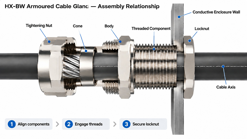
For armored or screened cables, proper earthing depends on how the cable gland is installed and connected to the enclosure. The gland makes contact with the cable armor or screen, while its metal body provides a connection to the enclosure through the mounting arrangement. Each connection needs to be secure and electrically conductive to maintain continuity.
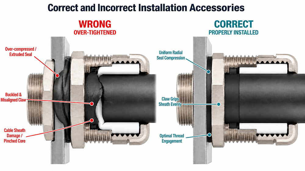
Problems can occur when the gland is fitted to a painted or coated metal enclosure. A standard locknut may not provide reliable electrical contact through the coating. A serrated locknut can help establish metal-to-metal contact, but it will not solve the problem if the cable gland itself is not designed to provide an earthing connection for armored or screened cables. Correct tightening is also important for keeping the gland securely mounted and maintaining the required seal.
Non-metallic enclosures need a different approach because the enclosure wall cannot provide an earth connection. In these installations, a grounding plate can provide a conductive connection point for the gland, provided it is properly connected to the protective earthing system. This is particularly important when replacing metal enclosures with plastic ones or modifying existing cable entries.
Common Cable Gland Earthing Problems
Most earthing continuity problems we hear about are related to installation rather than the cable gland itself. Here are four issues worth checking when a connection fails an earth continuity test:
Paint or Coatings Prevent Proper Contact
When a standard locknut is fitted against a painted enclosure, the coating can prevent reliable electrical contact between the gland and the metal wall. Depending on the installation, removing the coating around the mounting hole or using a suitable serrated locknut can help establish a conductive connection.
The Locknut Is Not Installed Correctly
Incorrect positioning or insufficient tightening can leave the gland loose, allowing it to move or rotate when the cable is handled. This can affect both the mechanical security of the installation and the electrical connection. The locknut should be fitted and tightened according to the gland manufacturer’s instructions.
The Gland Thread Is Too Short for the Enclosure Wall
If the threaded section does not extend far enough through the wall, stacking additional locknuts will not solve the problem. It may prevent the gland from being secured properly. A gland with a longer entry thread, or a suitable extension where permitted, is usually a better solution.
The Enclosure Is Not Properly Connected to Earth
Metal enclosures can provide a conductive connection when properly bonded, but this should not be assumed, especially with painted surfaces or composite enclosures. The earthing arrangement needs to be checked as part of the installation.
Frequently Asked Questions
Does every gland need a locknut?
Any gland entering an unthreaded clearance hole in an enclosure wall needs one, because the nut provides the inside bearing face and the locking action. Glands that mount directly into a tapped boss or a threaded bulkhead fitting are the exception.
Is a serrated locknut enough on its own for earthing?
It closes the bond through the wall where the wall is metal and the gland body carries the armor connection. It does not replace a dedicated earth conductor where the design or the local inspection calls for one.
Can a plain locknut be swapped for an EMC one later?
Yes, and the spanner sizes are the same, so the tool does not change. The wall coating has to be sound enough for the serrations to reach metal, which is worth checking before committing to a batch.
Do pipe thread glands use the same nuts?
They use the same series with G and NPT threads listed separately, from G1/2 to G3 and NPT1/2 to NPT3. The thickness values follow the same steps as the metric range.
Conclusion
Choosing the right cable gland locknut depends on more than thread size. The enclosure material, surface coating, and earthing requirements all need to be considered. A standard locknut may be suitable for some installations, while others require a serrated locknut to help maintain electrical continuity. It is also worth checking the enclosure wall thickness and gland thread length before ordering.
If you are having trouble with earth continuity during installation or testing, start by checking the locknut, the contact surface, and the enclosure’s earthing connection. These are common areas where problems occur.
How Can We Help You?
Our professional team is ready to provide you with prompt and support.

As a trusted cable gland supplier, our connector products serve international markets, including new energy, rail transportation, outdoor lighting, robotics and automation, industrial electrical cable equipment, and computer superservers.
© Copyright 2026 ZHEJIANG HONGXIANG CONNECTOR CO., LTD .