

blog
Cable Gland Size Chart for Armoured & Double Compression Glands


Choosing the right cable connector size is one of the most easily overlooked yet crucial steps in electrical installation. Whether you’re handling armored cables in heavy industry or wiring equipment in hazardous locations, selecting the right connector ensures mechanical tightness, environmental sealing, and long-term reliability.
Hoonsun Cable Gland manufactures a full range of brass, stainless steel, armored, double-clamp, and explosion-proof cable connectors designed for industrial applications. This article explains the principles of cable connector size selection, how to interpret cable connector size charts, and how to select the appropriate model for your project.
Why Cable Gland Sizing Matters?
A cable gland does more than secure a cable. It must:
- Maintain ingress protection
- Provide strain relief
- Bond or clamp armor when required
- Seal against moisture, dust, and corrosive elements
- Meet flame-retardant and explosion-proof standards when applicable
An undersized gland can damage cable insulation. An oversized gland can compromise sealing and IP ratings. Accurate sizing prevents both issues.
Key Factors in Cable Gland Selection
Before referencing any size chart, confirm the following:
1. Cable Type
- Unarmored cable
- Steel wire armored (SWA) cable
- Steel tape armored cable
- Double armored cable
2. Outer Diameter (OD)
The cable’s outer diameter determines the clamping range. Always measure the actual cable—not just the nominal size.
3. Thread Type
Common thread standards include:
- Metric
- PG threads
- NPT threads
- G (BSPP) threads
HXCableGland products support Metric, PG, G, and NPT threads depending on the model.
4. Application Environment
- General industrial use (IP54)
- Outdoor or washdown (IP68)
- Hazardous areas (Ex d IIC Gb)
- Flame-retardant requirements (UL94-V0)
Armoured Cable Gland Size Chart Overview
Cable connector sizes refer to a specific range of cable diameters that a connector is designed to securely accommodate and properly seal. Choosing the correct size is crucial for ensuring the reliable performance and long-term safety of any electrical system.
Choosing the appropriate cable connector size ensures:
Mechanical protection: protecting the cable from damage caused by tension, vibration, or torsion.
Environmental sealing: preventing dust, moisture, and gases from entering the electrical enclosure.
Electrical safety: ensuring proper grounding continuity and shielding, especially in armored cables.
Cable connector sizes are typically measured in millimeters (mm) and correspond to the cable’s outer diameter (OD). For example, if the cable’s OD is 20 mm, the selected cable connector size must accommodate a sealing range of 18–22 mm to ensure good clamping and sealing.
Choosing the wrong cable connector size can lead to improper installation, seal failure, and even electrical malfunctions. Therefore, engineers and installers always consult a reliable cable connector size guide before installation.
Below is a simplified interpretation of common armored gland ranges based on HXCableGland product specifications.
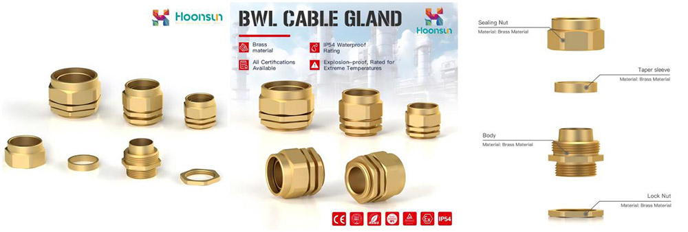
Example: BWL Armoured Cable Gland (Brass, IP54)
| Thread | Cable OD Min (mm) | Cable OD Max (mm) | Thread Length GL (mm) | Joint Length H (mm) | Spanner Size (mm) | Code |
| M20×1.5 | 14 | 21.1 | 10 | 17 | 24 | HX-BWL-20L |
| M20×1.5 | 11.7 | 16.1 | 10 | 17 | 22/23 | HX-BWL-20S |
| M25×1.5 | 20 | 27 | 10 | 23 | 34 | HX-BWL-25L |
| M25×1.5 | 19 | 24 | 10 | 23 | 31 | HX-BWL-25S |
| M32×1.5 | 26.2 | 33 | 10 | 23 | 40 | HX-BWL-32L |
| M32×1.5 | 24 | 30.5 | 10 | 23 | 36 | HX-BWL-32S |
| M40×1.5 | 32.5 | 41 | 10 | 25 | 45/48 | HX-BWL-40L |
| M50×1.5 | 44.1 | 55.7 | 15 | 32 | 55/63 | HX-BWL-50L |
| M63×1.5 | 56 | 68.2 | 15 | 38 | 78 | HX-BWL-63L |
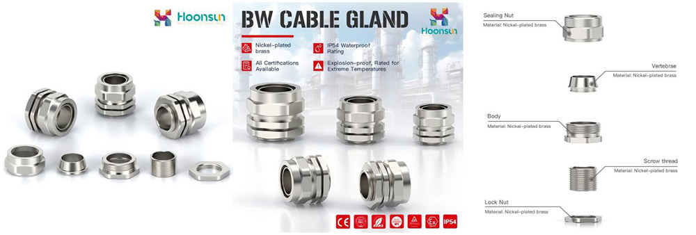
BW Series Armoured Cable Gland (Nickel-Plated Brass -IP54)
| Item | Thread | Cable OD Min (mm) | Cable OD Max (mm) | Thread Length (mm) | Joint Length (mm) | Spanner Size (mm) | Code |
| BW-0 | M20×1.5 | 12.6 | 16.5 | 10 | 23 | 22 | HX-BW0 |
| BW-1 | M20×1.5 | 15.9 | 19.0 | 10 | 26 | 27/25/24 | HX-BW1 |
| BW-2 | M25×1.5 | 20.6 | 26.5 | 10 | 29 | 35 | HX-BW2 |
| BW-3 | M32×1.5 | 26.5 | 33.0 | 10 | 32 | 40 | HX-BW3 |
| BW-4 | M40×1.5 | 34.9 | 40.5 | 15 | 36 | 50 | HX-BW4 |
| BW-5 | M50×1.5 | 44.5 | 51.0 | 15 | 45 | 64 | HX-BW5 |
| BW-6 | M63×1.5 | 57.0 | 67.0 | 15 | 50 | 82 | HX-BW6 |
Double Compression Armoured Cable Glands (IP68)
Double compression glands provide enhanced sealing and mechanical retention. They are ideal for:
- Outdoor installations
- Oil & gas facilities
- Marine applications
- High-vibration environments


Example: EX1 Armoured Explosion-Proof Gland
| Thread | Outer Sheath OD (mm) | Inner Sheath OD (mm) | Armor Range (mm) | Thread Length GL (mm) | Joint Length H (mm) | Code |
| M20×1.5 | 10–14 | 6–10 | 0.9/1.25 | 15 | 30 | HX-EX1.M20-14 |
| M20×1.5 | 13–18 | 9–14 | 0.9/1.25 | 15 | 32 | HX-EX1.M20-18 |
| M25×1.5 | 17–24 | 13–20 | 1.25/1.6 | 15 | 35 | HX-EX1.M25 |
| M32×1.5 | 23–32 | 18–26 | 1.6/2.0 | 15 | 39 | HX-EX1.M32 |
| M40×1.5 | 31–38 | 25–32 | 1.6/2.0 | 15 | 43 | HX-EX1.M40 |
| M50×1.5 | 37–44 | 31–38 | 1.8/2.5 | 15 | 48 | HX-EX1.M50 |
| M63×1.5 | 45–55 | 36–47 | 1.8/2.5 | 15 | 53 | HX-EX1.M63 |
EX3 Series Explosion-Proof Cable Clamp Sealing Joint
| Metric Thread | Inch Thread | Cable OD Range (mm) | Thread Length (mm) | Joint Length (mm) | Code |
| M16×1.5 | G3/8 | 7–15 | 15 | 53 | HX-EX3.M16-15 |
| M20×1.5 | G1/2 | 7–15 | 15 | 53 | HX-EX3.M20-15 |
| M25×1.5 | G3/4 | 11–20 | 15 | 53 | HX-EX3.M25-20 |
| M32×1.5 | G1 | 14–25 | 17 | 60 | HX-EX3.M32-25 |
| M40×1.5 | G1-1/4 | 19–33 | 17 | 70 | HX-EX3.M40-33 |
| M50×1.5 | G1-1/2 | 24–41 | 17 | 78 | HX-EX3.M50-41 |
| M63×1.5 | G2 | 30–50 | 17 | 82 | HX-EX3.M63-50 |
CW Series Simple Armored Cable Gland (IP54)
| Thread | Incoming Cable OD (mm) | Outgoing OD (mm) | Thread Length (mm) | Joint Length (mm) | Code |
| M20×1.5 | 14–20.9 | 16 | 10 | 35 | HX-CW-20L |
| M25×1.5 | 20–27 | 21.5 | 10 | 55 | HX-CW-25L |
| M32×1.5 | 26.2–33 | 27 | 10 | 55 | HX-CW-32L |
| M40×1.5 | 32.5–41 | 35 | 11 | 50 | HX-CW-40L |
| M50×1.5 | 44.1–53.1 | 45 | 15 | 57 | HX-CW-50L |
| M63×1.5 | 50–59.4 | 59 | 15 | 68 | HX-CW-63L |
How to Read a Cable Gland Size Chart?
When reviewing a size chart, focus on these columns:
1. Thread Size
Determines compatibility with enclosure entry hole.
2. Cable Outer Diameter Range
The most important measurement. Your cable OD must fall within this range.
3. Thread Length (GL)
Indicates how much threaded portion enters the enclosure.
4. Joint Length (H)
Overall compression length.
5. Spanner Size
Required wrench size for installation.
Common Mistakes When Reading a Cable Gland Chart
Assuming nominal cable size equals outer diameter
- Ignoring armor thickness
- Confusing Metric and NPT threads
- Overlooking enclosure wall thickness
- Choosing IP54 when IP68 is required
- Not verifying hazardous area certification
Conclusion
A cable gland size chart should never be read as a simple dimension list. It is a technical selection tool that ensures:
- Proper mechanical retention
- Long-term environmental sealing
- Regulatory compliance
- Electrical continuity
- Installation safety
When specifying glands for industrial or hazardous applications, always evaluate the complete parameter set, not just thread size. For full technical documentation, explosion-proof certifications, and engineering support, visit: https://www.hxcablegland.com/.
How Can We Help You?
Our professional team is ready to provide you with prompt and support.

As a trusted cable gland supplier, our connector products serve international markets, including new energy, rail transportation, outdoor lighting, robotics and automation, industrial electrical cable equipment, and computer superservers.
© Copyright 2026 ZHEJIANG HONGXIANG CONNECTOR CO., LTD .