

blog
PG7 vs PG9 vs PG11 Metal Cable Glands: How to Choose the Right Size


Many engineers mistakenly treat PG numbers as sequential size labels, assuming higher numbers simply mean larger, universally interchangeable glands. This misinterpretation is the leading cause of metal PG cable gland sizing errors in industrial projects.
In reality, PG is a standardised German thread specification code, where each size corresponds to a fixed mounting thread, through-hole diameter and compatible cable range. Mismatched sizing directly causes sealing failure, thread damage, cable pull-out and premature component degradation.
This guide breaks down the exact dimensional parameters of PG7, PG9 and PG11 metal cable glands, outlines common sizing mistakes, and provides a structured 3-step selection workflow to eliminate most preventable gland failures in industrial wiring.
Table of Contents
PG7 vs PG9 vs PG11 at a Glance
| Parameter | PG7 | PG9 | PG11 |
|---|---|---|---|
| Mounting Thread | M16 × 1.5 | M20 × 1.5 | M22 × 1.5 |
| Nominal Through-Hole Diameter | ~9.5mm | ~11.5mm | ~13.5mm |
| Compatible Cable Outer Diameter | 4mm – 6mm | 6mm – 8mm | 8mm – 10mm |
Understanding PG Cable Gland Sizing Standards
PG is not a generic “size number” but a standardised German thread specification for cable glands. Each PG rating corresponds to a precise set of dimensional parameters, including mounting thread size, through-hole diameter and compatible cable outer diameter range.
Sizing mismatch is one of the most common causes of premature gland failure in the field, leading to:
- Compromised IP sealing and ingress of dust / moisture
- Damaged panel threads and insufficient mechanical engagement
- Cable pull-out under tension or vibration
- Crushed internal conductors or loose cable retention
- Accelerated component degradation and shortened service life
A Practical Guide to PG7 Metal Cable Glands: Specs & Installation Tips
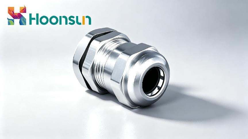
PG7 is the smallest standard PG size for industrial metal cable glands, optimised for small-gauge cables and compact installations.
Core Dimensional Parameters
- Mounting thread: M16 × 1.5
- Nominal through-hole diameter: ~9.5mm
- Compatible cable outer diameter range: 4mm – 6mm
Common Sizing Mistakes
The most frequent PG7 sizing error is confusing it with M12 threaded fittings. While both are used for small cables, PG7 has a significantly larger mounting thread diameter. Forcing a PG7 gland into an M12 panel hole results in insufficient thread engagement, drastically reduced tensile strength and compromised sealing performance.
Ideal Applications
PG7’s compact dimensions make it ideal for densely packed sensor and instrumentation housings, where multiple cable entries must fit into limited panel space. Its sealing system is calibrated specifically for thin cable jackets, delivering optimal compression without crushing delicate internal conductors in small-gauge signal wires.
PG9 Metal Cable Glands: Specifications, Mistakes & Applications
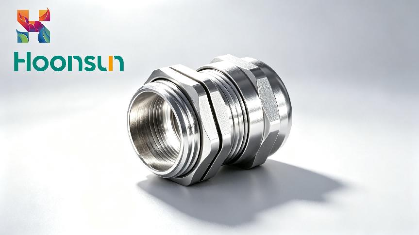
PG9 is the mid-range and most universally used PG specification, widely applied across general industrial wiring.
Core Dimensional Parameters
- Mounting thread: M20 × 1.5
- Nominal through-hole diameter: ~11.5mm
- Compatible cable outer diameter range: 6mm – 8mm
Common Sizing Mistakes
PG9 is the most frequently misapplied PG size, with two typical errors:
- Oversized cable: Using PG9 glands for cables over 8mm in diameter over-compresses the internal seal, causes permanent rubber deformation and leads to early cracking and leakage.
- Undersized cable: Installing cables under 6mm into PG9 fittings leaves insufficient compression, so the cable sits loose inside the gland. This allows water and dust to bypass the seal and gradually wears through the cable jacket from friction.
Because PG9 sits in the middle of the size range, it is often incorrectly used as a one-size-fits-all solution, even when cable diameters clearly fall outside its optimal range.
Ideal Applications
PG9 is the workhorse specification for general industrial control panels, distribution boxes and standard equipment cable entries where cable diameters fall within the 6–8mm range.
PG11 Metal Cable Glands: Specifications, Mistakes & Applications
PG11 is the larger heavy-duty PG size, engineered for heavier power cables and high-load applications.
Core Dimensional Parameters
- Mounting thread: M22 × 1.5
- Nominal through-hole diameter: ~13.5mm
- Compatible cable outer diameter range: 8mm – 10mm
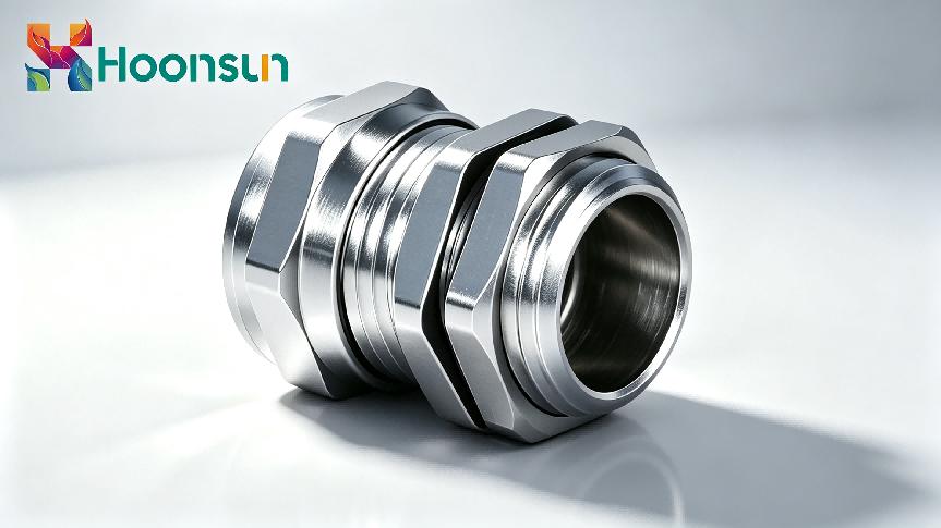
The larger thread diameter provides deeper panel engagement and higher mechanical load capacity, making it suitable for cables that experience higher pulling forces and vibration.
Common Sizing Mistakes
Many procurement teams standardise on PG11 across entire projects to reduce part numbers, assuming a larger gland will work safely with smaller cables. This practice:
- Wastes material cost on oversized components
- Creates hidden reliability risks, as internal clamping and sealing components cannot adapt to significantly smaller cable sizes
- Requires more panel space around each opening, causing clearance issues inside crowded equipment enclosures and making cable routing more difficult
Ideal Applications
PG11 is the standard for heavy industrial and outdoor power applications, including motor feeders, pump stations, outdoor charging infrastructure and solar combiner boxes. It is also preferred for steel wire armoured (SWA) cables that require higher clamping and retention force.
3-Step Correct Sizing Workflow for Metal PG Glands
Follow this structured, measurement-led selection process to eliminate sizing errors:
Step 1: Verify the panel opening and thread standard
First, measure the actual panel hole diameter and confirm the thread specification on the target enclosure. Never assume PG sizing based on hole size alone. For metal glands, always verify that thread engagement length is at least six full threads to guarantee mechanical strength and vibration resistance.
Step 2: Measure the full cable outer diameter
Measure the actual outer diameter of the finished cable, including the jacket, shield layer or armour — not just the nominal conductor cross-section.
Step 3: Select the matching PG size with adequate tolerance
Choose the PG size whose cable diameter range fully covers the measured dimension. Aim for the measured cable diameter to fall in the middle of the PG size’s stated range, leaving at least 0.5mm margin on both sides to accommodate jacket thickness variation and thermal expansion.
Key note: Each PG size’s internal compression geometry is calibrated for its specific cable range. Cross-sizing erodes sealing performance and shortens service life, even if the gland threads into the panel correctly.
FAQ
Q1: Are PG thread sizes interchangeable with metric M thread sizes of the same number?
A1: No. PG and metric M threads have different pitch and diameter specifications. For example, PG9 corresponds to M20×1.5, not M9. Mixing thread standards leads to poor engagement and unreliable performance.
Q2: Can I use reducing inserts to fit a smaller cable into a larger PG metal gland?
A2: Reducing adapters can work for temporary or low-demand applications, but they reduce sealing performance and tensile strength. For permanent industrial installations, selecting the correctly sized PG gland is always the more reliable solution.
Q3: How much cable diameter tolerance should I leave when selecting a PG size?
A3: Aim for the measured cable diameter to fall in the middle of the PG size’s stated range, leaving at least 0.5mm margin on both sides to accommodate jacket thickness variation and thermal expansion.
Conclusion
Accurate sizing of PG7, PG9 and PG11 metal cable glands relies on understanding PG as a thread specification rather than a sequential size number, and following a structured measurement-led selection process. Correct sizing ensures optimal sealing, mechanical strength and service life for every cable entry.
If you need support verifying PG sizing for your enclosures and cables, our technical team can provide dimension charts and on-request sizing verification for your project.
Need Help Verifying PG Sizing for Your Project?
Contact our technical team for dimension charts and on-request sizing verification for your enclosures and cables.
How Can We Help You?
Our professional team is ready to provide you with prompt and support.

As a trusted cable gland supplier, our connector products serve international markets, including new energy, rail transportation, outdoor lighting, robotics and automation, industrial electrical cable equipment, and computer superservers.
© Copyright 2026 ZHEJIANG HONGXIANG CONNECTOR CO., LTD .